HDMI 4K fiber optic cable
As is well known, optical fiber is much better than ordinary materials in terms of transmission distance and supports higher transmission rates, so many people will prioritize it when conditions permit. HDMI cables designed based on fiber optics fully leverage the advantages of fiber optics.
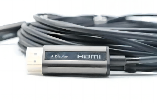
This length reaches an astonishing 15 meters, far exceeding most similar cables. In addition, it also achieves long-distance lossless transmission and supports 4K/60Hz video transmission. It is very suitable for use in home theaters, audio-visual entertainment, high-definition video conferencing office, multimedia education and other scenarios.
Next, we will disassemble it and see how the interior is designed.
1、Appearance of multimedia fiber optic cable
Product specifications:
Using a combination of 4-core optical fiber and 7-core tinned copper wire to prevent interference between high-frequency signals;
High quality photoelectric conversion module, ultra-low power consumption ≤ 250mW;
Supports 3D imaging and HDCP1.4/2.2;
The maximum resolution support is 3840 * 2160/60Hz, and it also supports downward compatibility with 1440P, 1080P, 1080I, and 720P;
Support audio feedback;
The color space supports up to YCBCr 4:4:4, with a color depth of 8 bits;
Long distance lossless transmission;
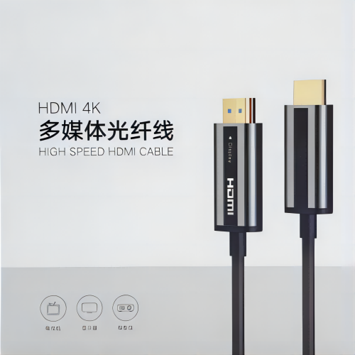
The male head cover is protected by a plastic shell, and the wire head shell is made of aluminum alloy and plastic materials, with a gray black color scheme. The middle area is designed with the words HDMI and Source, indicating that the cable is connected to the video output device.
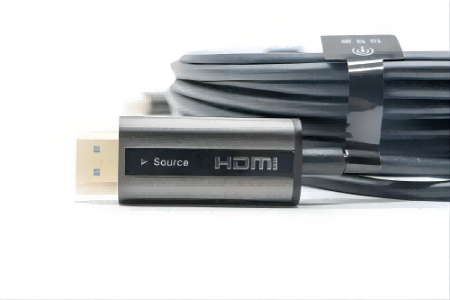
The design on the other end is the same, except that the Source has been changed to Display, indicating connection to the display. This design distinguishes the direction of transmission. Because fiber optic cables have directionality, there is a Source label that connects one end to the signal source output end, such as a laptop or host, and the other end to devices such as displays and projectors.
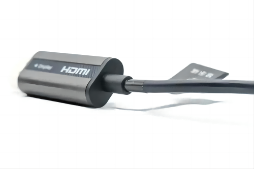
The end of the line has been extended for protection to prevent bending and skin bursting.
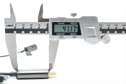
The measured length of the end is 41.17mm.
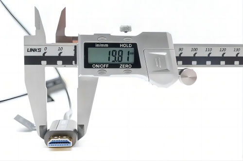
The width is 19.81mm.

The thickness is 10.84mm. Due to the built-in fiber optic transceiver circuit in the plug, the length of the plug is longer than that of traditional HDMI cable plugs.
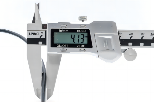
The diameter of the thread body is 4.13mm.
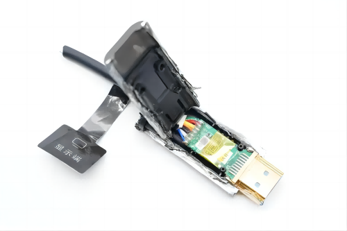
2、 Multimedia fiber optic cable disassembly
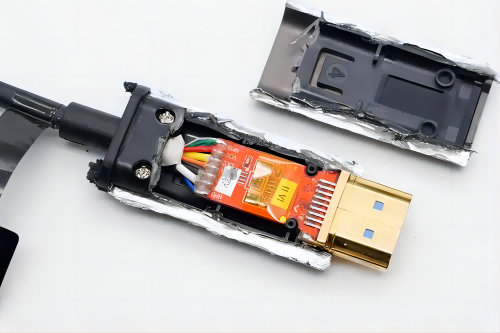
Cut open the aluminum alloy shell on the Source end, using a small red board inside. There is a plastic shell isolation between the board and the aluminum alloy shell.
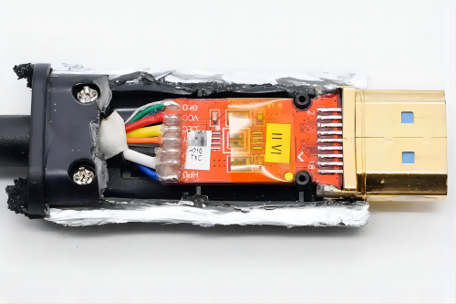
The small board is fixed with fixed columns, and the middle area is wrapped with insulation tape. The wire core welding points are protected by injection molding.
The end is also secured with screws to secure the wire core.
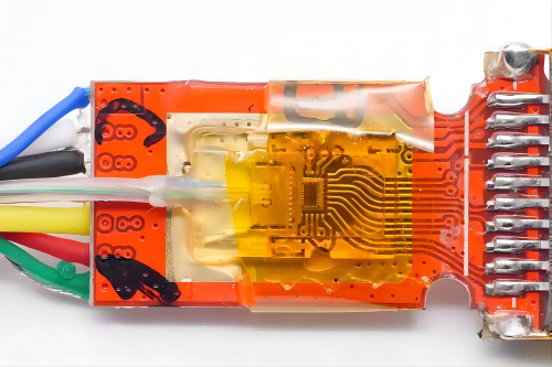
On the other side of the small board, copper is exposed in the central area, equipped with COB process drivers and VCSEL optoelectronic components. Four optical fibers are connected here and covered with microlenses, converging light into the optical fibers.
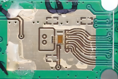
Close ups of four photoelectric components and drivers.
The display casing is also cut open, and the internal design is the same as the other end, but the small board is green to avoid confusion during production.
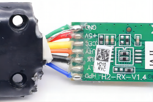
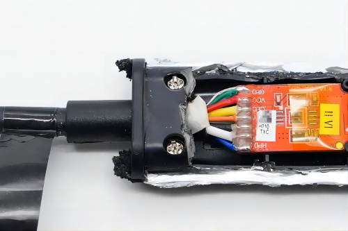
Close up of the wire core connection, from the silk screen on the right side of the wire core and actual measurement, it can be understood that:
The blue core function is Hot Plug Detection (HPD), which will serve as the basis for whether the HDMI Source initiates EDID reading and starts sending TMDS signals;
The white wire core is connected to the SCL pin, and the black wire core is connected to the SDA pin, used to communicate between the Source (DVD) and Display (TV);
The orange wire core is connected with reserved pins and not used;
The yellow core enables CEC signal connection, allowing users to control the devices connected on the HDMI interface;
The+5V symbol next to the red wire core indicates that it is a power wire core;
The green wire core and the exposed wire core are connected in one place, with the function of DDC/CEC grounding;
Fiber optic cores are used for transmitting three pairs of TMDS data and one pair of clock signals.
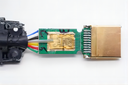
On the other side of the board, there are also COB process drivers and optoelectronic components.
Cut the thread body.
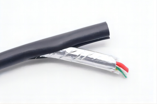
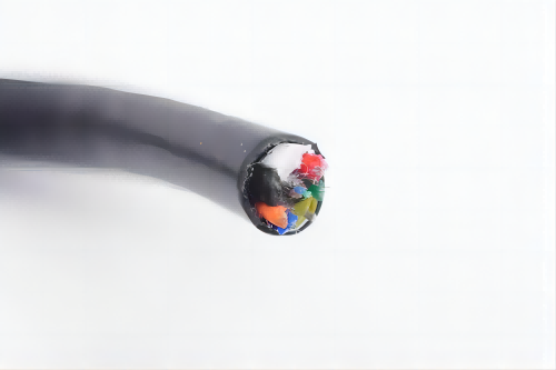
The wire core group is wrapped in tin foil to shield interference.
The wire core group is mixed with multiple anti pull wires to improve the cable's tensile performance.
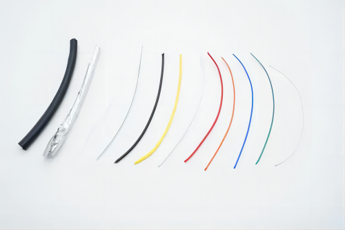
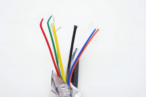
Take a cut of the cable core, which is the same as the official specifications, with 4 fiber optic cables and 7 tinned copper cable cores, as well as one exposed cable core and three anti pull wires.
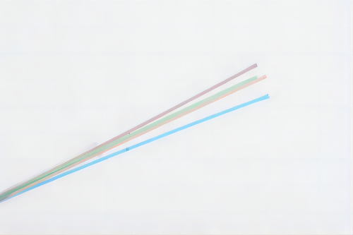
Close ups of four fiber optic cables, each with a different color, covered with an insulating plastic layer, used for digital signal transmission.
Through disassembly, it was found that as shown in the packaging specifications, both ends of the cable are equipped with high-quality photoelectric conversion modules, and four optical fibers are connected. The remaining 8 wire cores are all tin plated to resist interference, and in addition, three anti pull wires are added to the cable to improve tensile performance. This HDMI cable is based on fiber optics and can achieve lossless transmission. Compared to ordinary copper cable versions, it has a qualitative improvement in both length and transmission performance, meeting various high demand scenarios.